De-soldering components (through-hole and SMD)
SMT parts have many advantages over their older through hole ancestors, namely: smaller size, lower cost manufacturing costs, and less likelihood of obsolescence. However, an often overlooked advantage is the ease at which surface mount components can be soldered and desoldered. At first this might seem like a controversial subject, but it isn’t to engineers and technicians to have grown accustomed to working with both types of parts. Just try desoldering a 16 pin DIP from a PCB with a solder sucker without ripping a trace, and you’ll understand how hard reworking a through hole part can be. Compare this to a desoldering a 16 pin SOIC which can be removed in a matter of seconds with no special equipment.
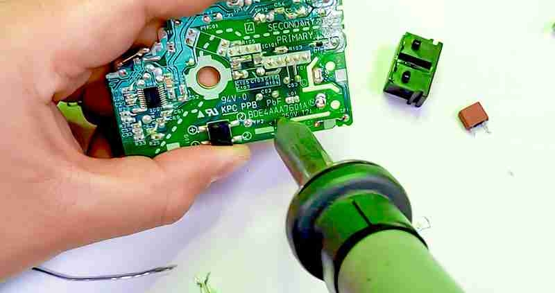
Vacuum Desoldering
The vacuum based through-hole desoldering station consisted of a soldering iron with a hollow tip and body which leads to a glass tube capped by a filer at one end which is also the end the vacuum is applied to. The trick is to heat up the whole solder joint (I use an ample amount of flux to assist) and then start the vacuum by pulling the trigger. During this time I am also wiggling the soldering iron tip in order to break the component pin free from the wall of the hole or plate-through. Done correctly both the PCB and the component being removed are reusable.
Infrared Desoldering
The infrared based system, referred to as an Infrared Welder by the manufacturer, can ultimately heat a smaller area to a hotter temperature than hot air, or so I believe. To mask off the surrounding area for hot air you need to keep your airflow low and redirect it away from the rest of the PCB. To redirect Infrared you use the reflective properties of aluminum foil. It’s then mostly a matter of firing up the fume fan and having the patience to wait for the direct heat to do the job. Again a judicious use of flux helps.
Hot Air Desoldering
Hot Air is similar in that flux helps, fumes and smoke may be present and you have to have the patience to wait for the part to come fully loose — half loose doesn’t cut it. To this end I recommend a hot air holder, a fume fan and an egg timer. If you don’t have an egg timer I am sure there is an app for that somewhere.
Desoldering with Chip Quik and an iron
I have found The quickest way to desolder SMT without investing in any of this equipment is to use a product which lowers the melting point of the solder metal when mixed with it as it allows a soldering iron to melt the entire chip’s footprint simultaneously allowing it to be removed.