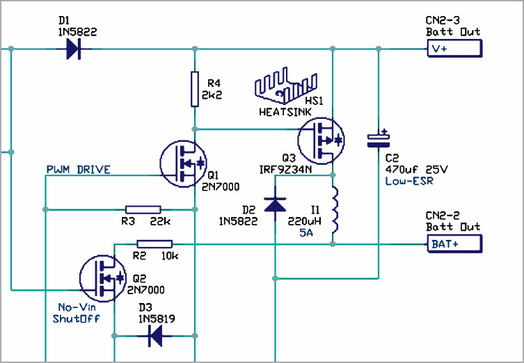
Schematic Diagram
After you define the specification and fuction, next step is called is called a schematic releasing or circuit diagram. It is always constructed in CAD format. we often use Protel CAD to realize the PCB schematic diagram. Schematic diagrams are constructed according to a number of standards and rules, but the primary function is to explain the circuit design in an easily form.
- Specializes in schematic capture and PCB layout design services
- Cost-effective function development solutions.
- Remote management, high-speed signaling Features
- Utilizing 64-bit microprocessors (CPUs and NPUs) and routing constraints
- Supporting high-power processors and high-speed interconnects
- 0201 / 01005-sized components and 0.8mm-pitch BGAs
- Original materials, design rules, and lastest practices
- Quick Turn PCB design
What C-alley can offer over PCB schematic diagram?
Schematics Diagram is a service provided by C-alley PCB Design that involves creating schematic diagrams for electronic devices.
Schematic diagrams are a visual representation of the electrical connections and components in a circuit. They are an essential part of the design process for electronic devices, as they allow designers to understand how the circuit works and identify potential problems before the circuit is built.
C-alley Schematics Diagram tool includes a variety of software tools that are used to create high-quality schematic diagrams for electronic devices. Some of the tools that C-alley PCB Design uses include:
Altium Designer: A comprehensive PCB design software that allows designers to create schematic diagrams, PCB layouts, and 3D models.
Eagle PCB Design: A popular PCB design software that is widely used for creating schematic diagrams and PCB layouts.
KiCAD: An open-source PCB design software that includes a schematic capture tool, a PCB layout tool, and a 3D viewer.


